Orders placed today ship out in 5-7 business days. Due to heavy demand, we can't guarantee arrival by Christmas.
Head-Switching Noise & Overscanned Images
In a VCR, as the pair of video heads spin, one head reads from the tape, then the other head takes over. The head-switching controls the timing of when the heads switch between each other. If the head switching occurs too early, the head switching noise will appear higher up, and will be visible at the bottom of the picture. If the head switching is late, it will overlap the sync which will cause vertical jitter in the picture. Head switching timing is also critical in achieving correct Hi-Fi sound, which is derived from a additional set of spinning Hi-Fi heads.
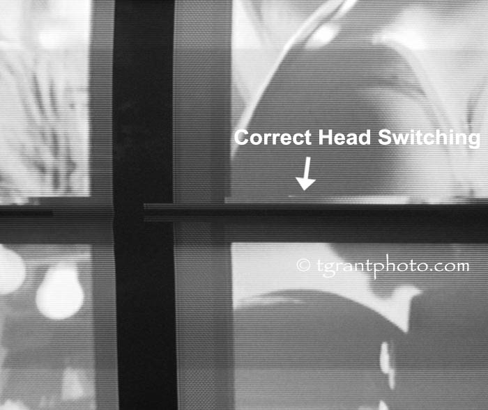
To properly set the head switching we use a waveform monitor and pulse-cross display monitor to view and adjust the video head envelopes. The pulse-cross image (shown below) shows the hidden areas at the top and bottom of a TV picture. The normal head switching position is shown below.

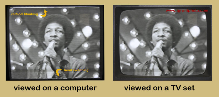
Most VCRs and video processors manufactured in the 90's and earlier, were designed for analog NTSC TV standards, under which images were shown underscanned on the TV sets of the day. This had the benefit of hiding various defects in the TV picture, such as videotape head switching noise, which appears at the bottom of a TV image. This was all hidden because analog TVs and video monitors were purposely set to underscan (or not show) the edges of the image. Computer capture cards, however, show the very outermost edges of all the available picture, even the video head-switching noise at the bottom of the screen!

It doesn't indicate a problem with your VCR if you see the head-switching noise at the bottom of your computer monitor. These lines of “noise” are present on all VCR playbacks. On a computer, you're seeing the entire image, not the cropped version that TV viewers in the 1990's would see.
Most people capturing video onto a computer correct this by either masking or cropping the captured image. This can be done with a software program, allowing you to present the image in its intended form, without the head-switching noise at the bottom of the screen. If you do crop the image, remember to maintain the original aspect ratio. Trim from the sides as well as the bottom to maintain the correct picture ratio. If you have the wrong aspect ratio, people in the resulting image will look slightly fatter!
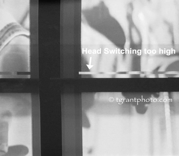
If the VCR's head switching is set incorrectly, the head switching can move up into the viewable area at the bottom of the TV screen (see photo below)

Conversely, if the head switching is set too low it can move down into the vertical sync (the black horizontal bar in the photo). This will cause vertical jitter in the picture and problems with the hi-fi sound. NOTE: some videotapes may display slightly higher or lower head switching, this can be attributed to the alignment of the particular VCR that recorded the tape.
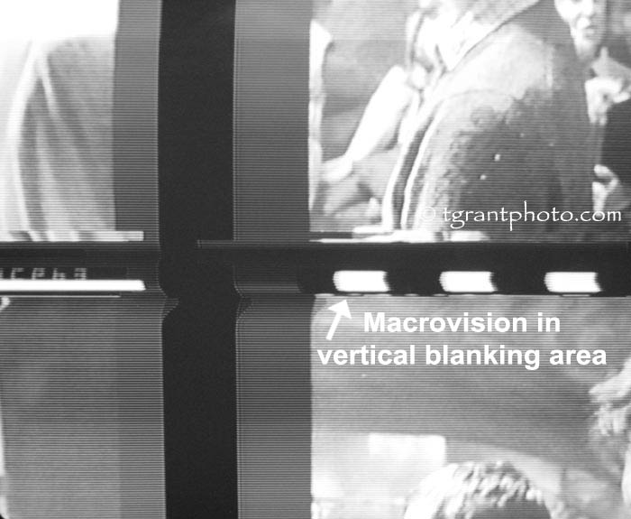
Below is an example of the Macrovision copy guard process which puts Pseudo-Sync Pulses into the vertical blanking area. Although viewable on computer captures, these pulses are hidden in the non-viewable area at the top of regular TV screens.

Note: The above content is copyright TGrant Photo LLC.. Copying or use on another website is prohibited.
